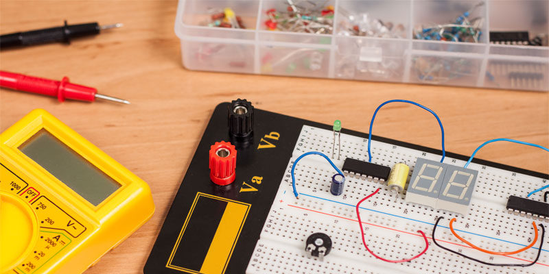
Learning about basic electronics and creating your own projects is a lot easier than you may think. In this tutorial, we’re going to give you a brief overview of common electronic components and explain what their functions are. You will then learn about schematic diagrams and how they are used to design and build circuits. And finally, you will put this information to use by creating your first basic circuit.
FREE EBOOK (PDF) – Makerspace Info Bundle
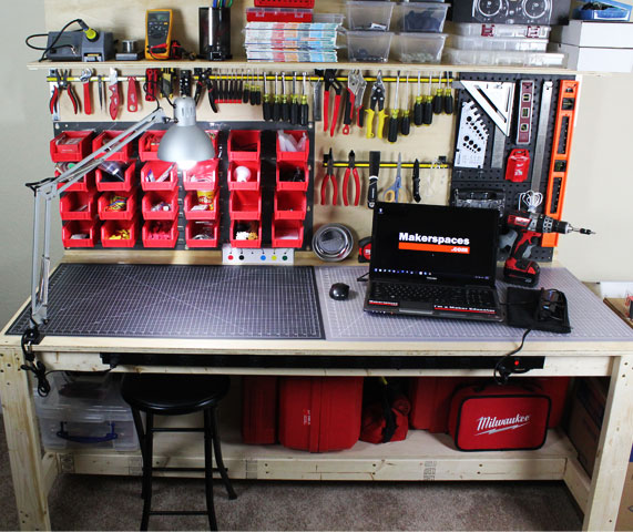
Electronic Workbench
Before you get started, make sure your electronic workbench is properly set up. The work area doesn’t need to be fancy and you could even build your own electronic workbench.
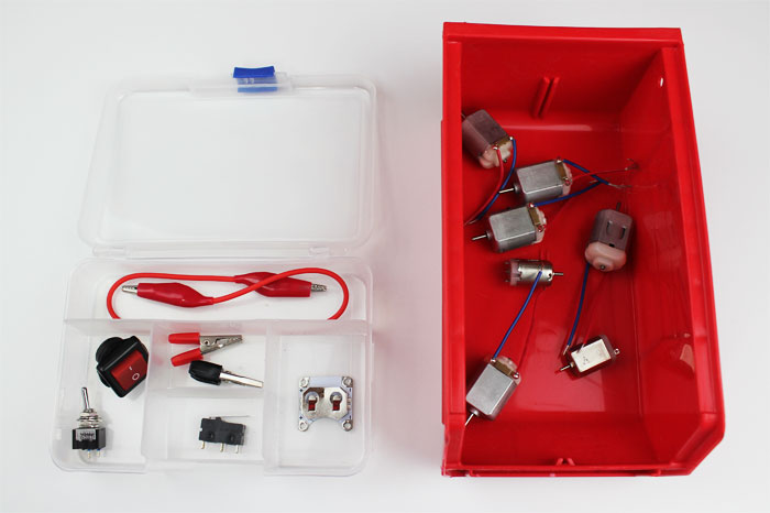
Storage
Electronic components can be small and it’s a good idea to keep everything organized. The most popular option is to use clear plastic storage boxes for storing parts. In addition, you could use plastic storage bins that hang from a rack or fit on a shelf.
Tools
Now that you have a good workspace set up, it’s time to stock it with the proper tools and equipment. This isn’t a complete list but it does highlight the most common items used in electronics.
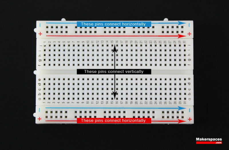
Breadboard
Breadboards are an essential tool for prototyping and building temporary circuits. These boards contain holes for inserting wire and components. Because of their temporary nature, they allow you to create circuits without soldering. The holes in a breadboard are connected in rows both horizontally and vertically as shown below.
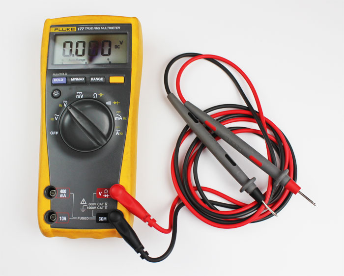
Digital Multimeter
A multimeter is a device that’s used to measure electric current (amps), voltage (volts) and resistance (ohms). It’s a great for troubleshooting circuits and is capable of measuring both AC and DC voltage. Check out this post for more info on how to use a multimeter.
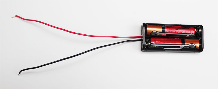
Battery Holders
A battery holder is a plastic case that holds batteries from 9V to AA. Some holders are enclosed and may have an on/off switch built in.
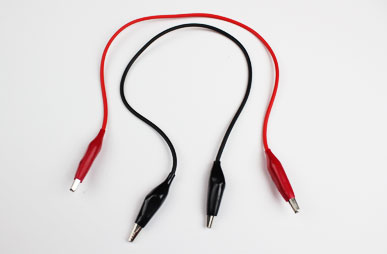
Test Leads (Alligator Clips)
Test leads are great for connecting components together to test a circuit without the need for soldering.
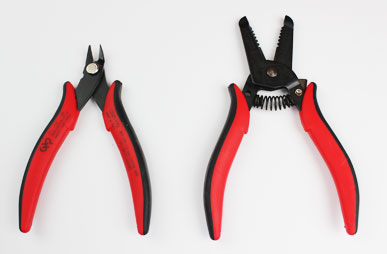
Wire Cutter
Wire cutters are essential for stripping stranded and solid copper wire.
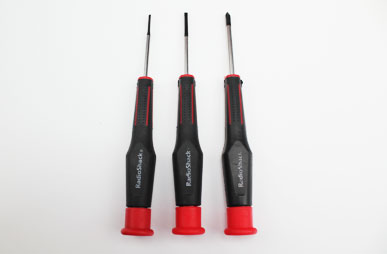
Precision Screwdriver Set
Precision screwdrivers are also known as jeweler’s screwdrivers and usually come as a set. The advantage of these over normal screwdrivers is the precision tips of each driver. These are very handy when working with electronics that contain tiny screws.
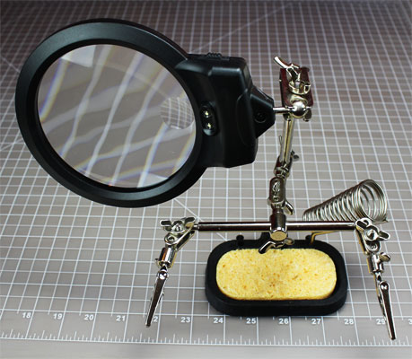
Helping 3rd Hand
When working with electronics, it seems you never have enough hands to hold everything. This is where the helping hand (3rd hand) comes in. Great for holding circuit boards or wire when soldering or tinning.
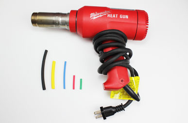
Heat Gun
A heat gun is used to shrink plastic tubing known as heat shrink to help protect exposed wire. Heat shrink has been called the duct tape of electronics and comes in handy in a wide variety of applications.
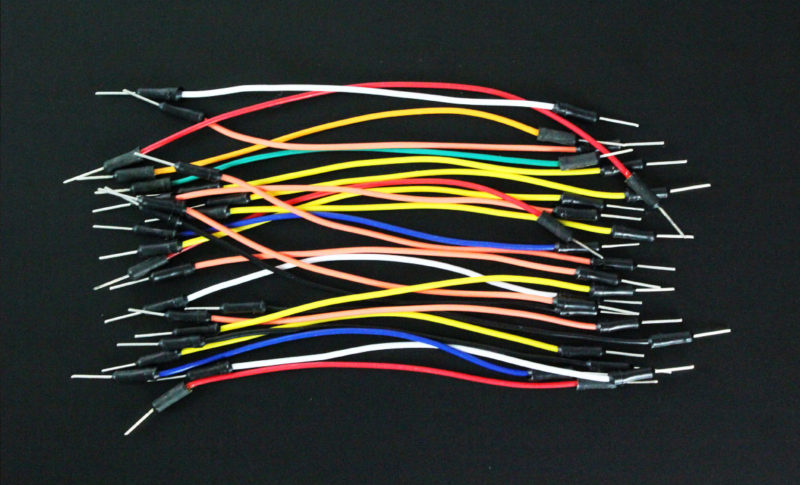
Jumper Wire
These wires are used with breadboard and development boards and are generally 22-28 AWG solid core wire. Jumper wires can have male or female ends depending on how they need to be used.
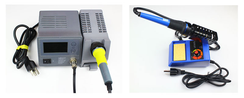
Soldering Iron
When it time to create a permanent circuit, you’ll want to solder the parts together. To do this, a soldering iron is the tool you would use. Of course a soldering iron isn’t any good unless you have solder to go with it. You can choose leaded or lead-free solder in a few diameters.
Electronic Components
Now its time to talk about the different components that make your electronic projects come to life. Below is a quick breakdown of the most common components and functions they perform.
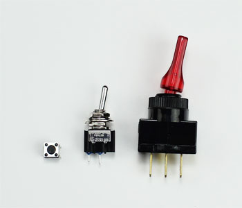
Switch
Switches can come in many forms such as pushbutton, rocker, momentary and others. Their basic function is to interrupt electric current by turning a circuit on or off.
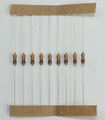
Resistor
Resistors are used to resist the flow of current or to control the voltage in a circuit. The amount of resistance that a resistor offers is measured in Ohms. Most resistors have colored stripes on the outside and this code will tell you it’s value of resistance. You can use a multimeter or Digikey’s resistor color code calculator to determine the value of a resistor.
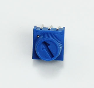
Variable Resistor (Potentiometer)
A variable resistor is also known as a potentiometer. These components can be found in devices such as a light dimmer or volume control for a radio. When you turn the shaft of a potentiometer the resistance changes in the circuit.
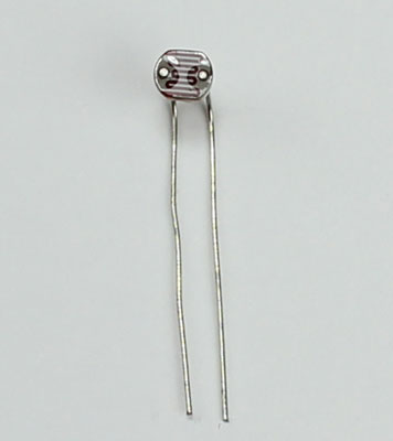
Light-Dependent Resistor (LDR)
A light-dependent resistor is also a variable resistor but is controlled by the light versus turning a knob. The resistance in the circuit changes with the intensity of the light. These are often found in exterior lights that automatically turn on at dusk and off at dawn.
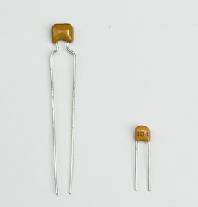
Capacitor
Capacitors store electricity and then discharges it back into the circuit when there is a drop in voltage. A capacitor is like a rechargeable battery and can be charged and then discharged. The value is measured in F (Farad), nano Farad (nF) or pico Farad (pF) range.
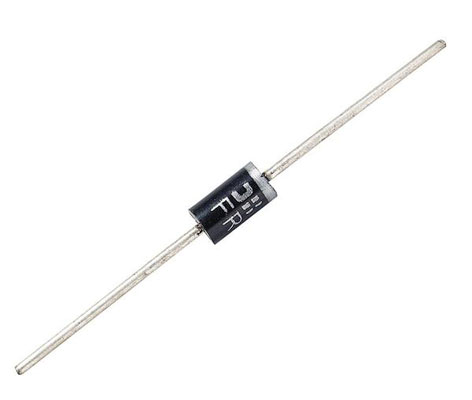
Diode
A diode allows electricity to flow in one direction and blocks it from flowing the opposite way. The diode’s primary role is to route electricity from taking an unwanted path within the circuit.
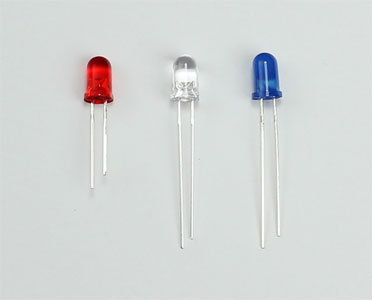
Light-Emitting Diode (LED)
A light-emitting diode is like a standard diode in the fact that electrical current only flows in one direction. The main difference is an LED will emit light when electricity flows through it. Inside an LED there is an anode and cathode. Current always flows from the anode (+) to the cathode (-) and never in the opposite direction. The longer leg of the LED is the positive (anode) side.
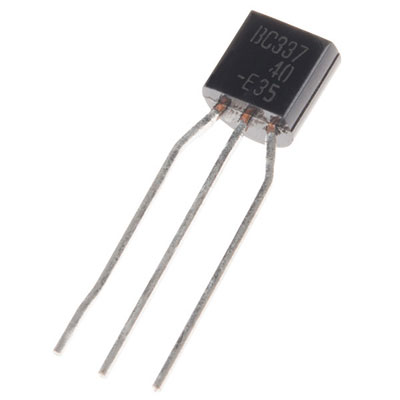
Transistor
Transistor are tiny switches that turn a current on or off when triggered by an electric signal. In addition to being a switch, it can also be used to amplify electronic signals. A transistor is similar to a relay except with no moving parts.
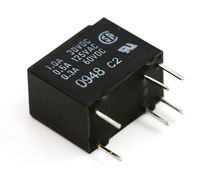
Relay
A relay is an electrically operated switch that opens or closes when power is applied. Inside a relay is an electromagnet which controls a mechanical switch.
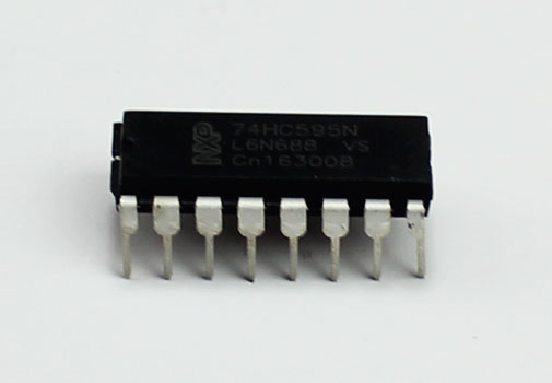
Integrated Circuit (IC)
An integrated circuit is a circuit that’s been reduced in size to fit inside a tiny chip. This circuit contains electronic components like resistors and capacitors but on a much smaller scale. Integrated circuits come in different variations such as 555 timers, voltage regulators, microcontrollers and many more. Each pin on an IC is unique in terms of it’s function.
What Is A Circuit?
Before you design an electronic project, you need to know what a circuit is and how to create one properly.
An electronic circuit is a circular path of conductors by which electric current can flow. A closed circuit is like a circle because it starts and ends at the same point forming a complete loop. Furthermore, a closed circuit allows electricity to flow from the (+) power to the (-) ground uninterrupted.
In contrast, if there is any break in the flow of electricity, this is known as an open circuit. As shown below, a switch in a circuit can cause it to be open or closed depending on it’s position.
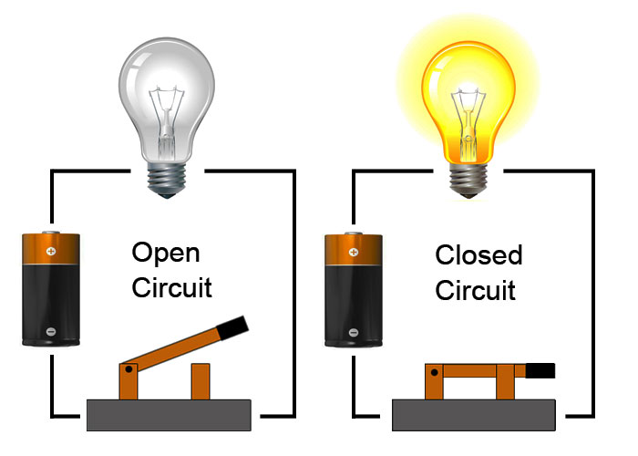
All circuits need to have three basic elements. These elements are a voltage source, conductive path and a load.
The voltage source, such as a battery, is needed in order to cause the current to flow through the circuit. In addition, there needs to be a conductive path that provides a route for the electricity to flow. Finally, a proper circuit needs a load that consumes the power. The load in the above circuit is the light bulb.
Schematic Diagram
When working with circuits, you will often find something called a schematic diagram. These diagrams use symbols to illustrate what electronic components are used and where they’re placed in the circuit. These symbols are graphic representations of the actual electronic components.
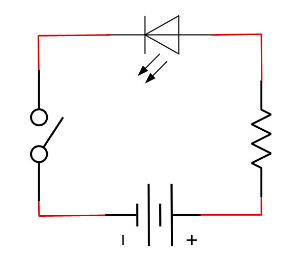
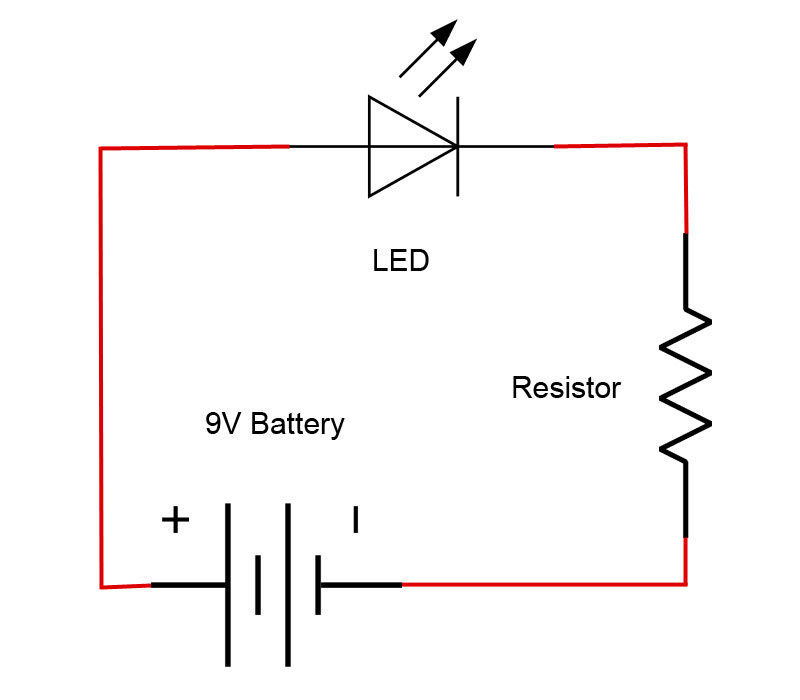
Below is an example of a schematic that depicts an LED circuit that is controlled by a switch. It contains symbols for an LED, resistor, battery and a switch. By following a schematic diagram, you are able to know which components to use and where to put them. These schematics are extremely helpful for beginners when first learning circuits.
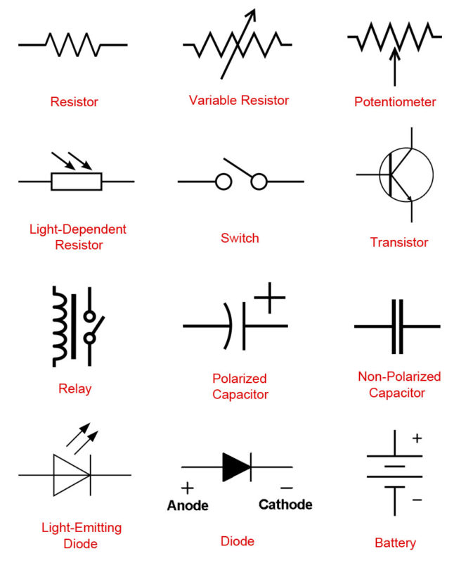
There are many types of electronic symbols and they vary slightly between countries. Below are a few of the most commonly used electronic symbols in the US.
How To Determine A Resistor Size
Resistors are commonly used in electronics projects and it’s important to know which size to use. To find the resistor value, you need to know the voltage and the amps for your LED and battery.
A standard LED generally needs a voltage of around 2V and a current of 20mA or .02A to operate correctly. Next, you need to find out what voltage your battery is. In this example, we will be using a 9V battery. In order to determine the resistor size, we need to use a formula known as Ohm’s law as shown below.
Ohm’s Law – Resistance (R) = Voltage (V) / Current (I)
- Resistance is measured in Ohms (Ω)
- Voltage is measured in volts (V)
- Current is measured in amps (A)
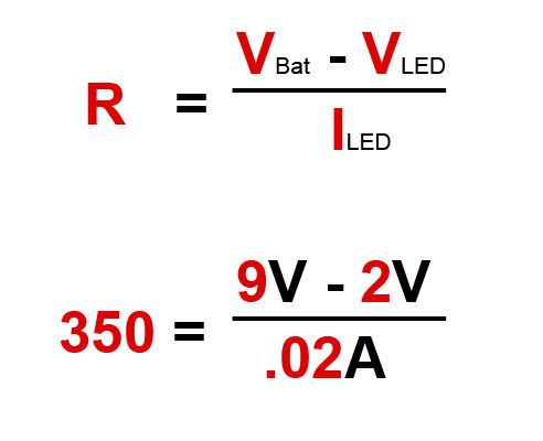
Using Ohm’s law, you need to subtract the LED voltage from the battery voltage. This will give you a voltage of 7 which needs to be divided by .02 amps from the LED. This formula shows that you will need a 350 Ω resistor.
As a note, standard resistors don’t come in 350 Ω but are available in 330 Ω which will work fine.
Electronics Project #1
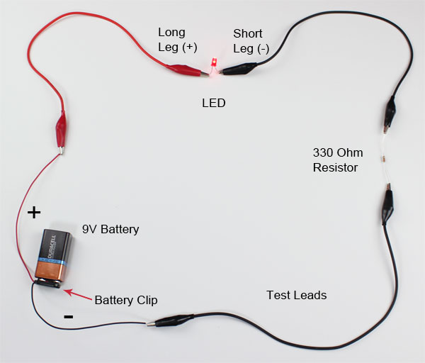
Now it’s time to combine everything you’ve learned and create a basic circuit. This project is a great starter project for beginners. We will be using test leads to create a temporary circuit without having to solder it together.
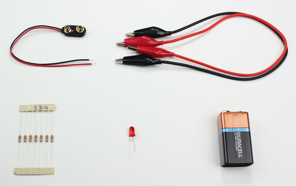
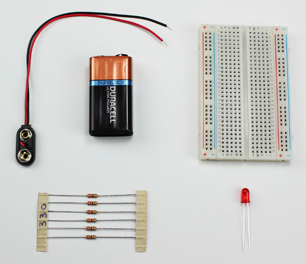
Parts Needed:
- 9V Battery
- Battery Snap-on Connector
- Test Leads w/ Alligator Clips
- 330 Ohm Resistor
- LED – Basic Red 5mm
Schematic Diagram
Project Steps
- Attach the battery clip to the top of the 9V battery.
- Red wire from the battery clip is connected to one alligator clip on the red test lead.
- The other end of the red test lead is connected to the long leg (+) of the LED.
- Connect one alligator clip from black test lead to the short leg (-) of the LED.
- The other end of the black test lead is clipped to one leg of the 330 Ω resistor.
- Clip one side of the other black test lead to the other leg of the 330 Ω resistor.
- The opposite end of the black test lead is connected to the black battery wire.
IMPORTANT – Never connect an LED directly to a 9V battery without a resistor in the circuit. Doing so with damage/destroy the LED. You can however connect an LED to a 3V or smaller battery without a resistor.
How To Use A Breadboard
Another way to create and test a circuit is to build it on a breadboard. These boards are essential for testing and prototyping circuits because no soldering is needed. Components and wires are pushed into the holes to form a temporary circuit. Because it’s not permanent, you can experiment and make changes until the desired outcome is reached.
Below the holes of each row are metal clips that connect the holes to each other. The middle rows run vertically as shown while the exterior columns are connected horizontally. These exterior columns are called power rails and are used to receive and provide power to the board.
Breadboards will need to have power supplied to them and this can be done in a few ways. One of the easiest way is to plug the wires from a battery holder into the power rails. This will supply voltage to the rail it’s plugged into only.
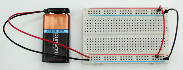
To power both rails, you will need to use a jumper wire from the (+) and (-) to the rail on the opposite side.
Electronics Project #2
Now we’re going to learn how to create a circuit on a breadboard. This circuit is the exact same one we did earlier but we won’t be using the test leads.
Parts Needed:
Schematic Diagram
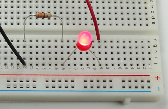
Project Steps
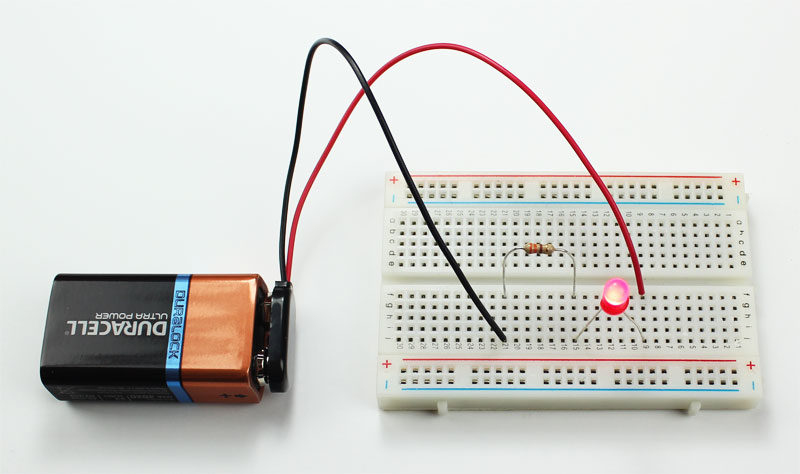
- Attach the battery clip to the top of the 9V battery.
- Place the red wire from the battery clip into F9 of the breadboard.
- Insert the black wire from the battery clip into J21 of the breadboard.
- Bend the legs of the 330 Ω resistor and place one leg into F21.
- Place the other leg of the resistor into F15.
- Insert the short leg of the LED into J15 and the long leg into J9.
The red arrows in the image below help to show how electricity is flowing in this circuit. All components are connected to each other in a circle just like when we used the test leads.
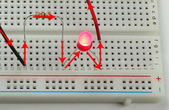
IMPORTANT – Never connect an LED directly to a 9V battery without a resistor in the circuit. Doing so with damage/destroy the LED.
How To Solder
If you want to make your circuit permanent, you’ll need to solder it together. For an in-depth tutorial on soldering electronics, view our post How To Solder for a complete step-by-step guide.
Electronics Supply
There are a lot of great places online to find electronic components, parts and tools. Below is a list of our favorite places to shop for electronics.